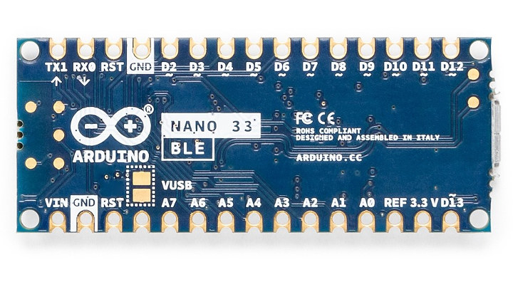
When the pin is set LOW or 0, the LED turns OFF. When this pin is set HIGH or 1, the LED turns ON. Pin 13 LED Indicator (Blue): In the board, there is a built-in LED connected to digital pin 13. It can also display the voltage of the battery onto the LCD connected to the Arduino board. Power Indicator: It indicates the status of the battery. Receiving Data Indicator LED (Red): When this LED lights up, the board is receiving data from the computer. Transmitting Data Indicator LED (White): When this LED ON, the Arduino Nano is transmitting data to the computer. LED Indicators on Arduino Nano:Īrduino Nano board consist of 4 LED indicators: Sending a signal to this pin does nothing. It provides the voltage reference at which the microcontroller is currently operating. REF: This pin is the input/output reference. If this pin is supplied with 5 V, the board will reset automatically GND (Ground pins): There is a total of 5 ground pins on the board. UART pins on board: D0(TX), D1(RX) Other pins: It also represents the successful flow of data from the computer to the board.
Canbus to arduino nano pinout serial#
The TXD is used for transmitting the data, and RXD is used for receiving the data during serial communication. UART Pins: TXD and RXD pins are used for serial communication. This allows us to have multiple SPI peripheral devices sharing the same MISO, MOSI, and CLK lines.Įxternal Interrupts (2 and 3)- These pins can be used to trigger an external interrupt in the following conditions: a low value, a rising or falling edge, or a change in value. When its value HIGH, it ignores the master. When a device’s Slave Select pin value is LOW, it can communicate with the master. This line is used for sending data to the peripherals.

The device supports up to 5Mbps data rate in CAN FD mode allowing much faster transfer of payload compared to classic CAN. The ISO1042 device offers ☗0-V DC bus fault protection and ☓0-V common-mode voltage range. The ISO1042 device is a galvanically-isolated controller area network (CAN) transceiver that meets the specifications of the ISO11898-2 (2016) standard. Atmega32U4 with Arduino Leonardo bootloader on the board MCP2515 CAN Bus controller and MCP2551 CAN Bus transceiver OBD-II and CAN standard pinout selectable. D1 Power LED, CN1 Can bus communication, CN3 RJ45 CAN Communication. The project supports up to 5Mbps data rate in CAN FD mode allowing much faster transfer of payload compared to classic CAN.

The project requires 5V supply from the host side (Arduino) and separates 5V from the node side for isolation. The project built using ISO1042 IC from Texas Instruments. The high-speed controller area network transceivers offer integrated isolation, high ESD and high fault protection. A controller area network is a two-wire high-speed serial network typically used to provide data communication between host and nodes. This module can be used as a standalone module or as an Arduino Uno shield. The module described here is an isolated CAN Transceiver module.


 0 kommentar(er)
